Inter-Kubernetes Networking with Forwarded DNS
How to configure clusters that can be used securely between different regions or clouds.
|
Tutorials are accurate at the time of writing but rely heavily on third party software. Tutorials are provided to demonstrate how a particular problem may be solved. Use of third party software is not supported by Couchbase. For further help in the event of a problem, contact the relevant software maintainer. |
It is often desirable to have clients connect to a Couchbase cluster from outside of the hosting Kubernetes cluster. The specific scenario this tutorial will address is where a client resides within another Kubernetes instance. Such a topology may be used in the following situations:
-
Geographically dispersed clients can connect into a centralized database instance.
-
Cross center replication (XDCR) can be used to replicate or backup data to a different geographical region, even cloud provider.
-
General partitioning of workloads into security zones.
Because your data is valuable, it should always be encrypted in transit — even across a secure VPN — so this tutorial will deal exclusively with TLS.
TLS — with the Operator — is driven exclusively with DNS wildcard certificates. A wildcard certificate is valid for all nodes that a Couchbase cluster contains and will contain as the topology changes during the cluster lifetime. The Operator does not support IP based certificates as that would require the Operator to act as a certificate signing authority, which is a security concern. Additionally IP addresses cannot be known before a pod is created and the TLS secrets mounted, adding complexity.
As such TLS support outside of the Kubernetes cluster is driven by DNS. Consider the following architecture diagram:
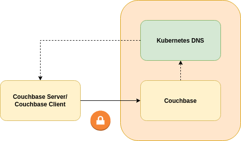
The client uses DNS addresses served by its local Kubernetes DNS server for normal in-cluster operation. It also uses those in a remote Kubernetes DNS server in order to resolve the IP addresses of the remote Couchbase cluster. This means that the remote cluster must use a different subnet than the local one so network addresses are unique. This means that the remote cluster must use flat, routed networking; a pod in the local cluster must be able to connect to a pod in the remote cluster without DNAT.
For the purposes of this tutorial we will use CoreDNS as a proxy DNS server for Couchbase Server pods. This will then selectively forward requests on to either the local or remote DNS server instances. CoreDNS is readily available, and already powers most of the managed Kubernetes offerings. Other DNS servers may be used (e.g. BIND), provided they can forward specific zones to a remote DNS server.
|
While this tutorial focuses on Kubernetes to Kubernetes connectivity, the client need not reside in Kubernetes. The same rules however apply; no DNAT between the client and Couchbase server instance, and clients use a local DNS server to separate traffic and forward to the correct recipient. |
Configuring the Platform
Platform configuration is left up to the end user as there are numerous different ways of deploying and interconnecting your Kubernetes clusters.
The following diagram is based on eksctl for Amazon AWS, however the concepts will be generally the same for any platform:
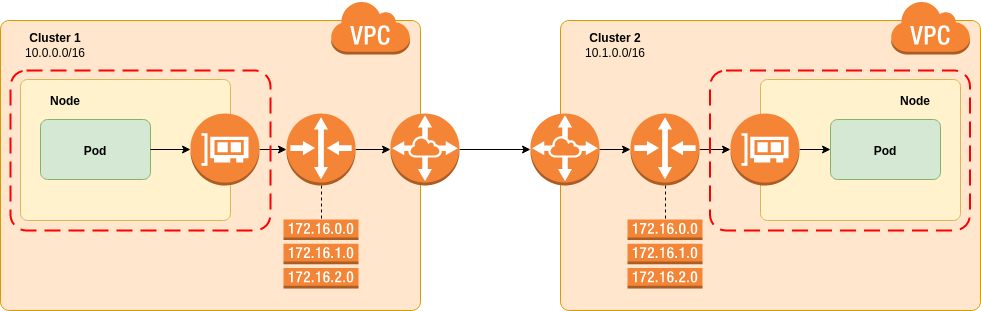
The eksctl tool creates clusters similar to those depicted.
It uses the amazon-vpc-cni-k8s CNI plugin to provision pod network interfaces.
Pod interfaces are provisioned using elastic network interfaces, so appear as part of the cluster VPC.
No overlay networks are involved and the pod IP addresses can be reached from outside of the Kubernetes cluster without NAT.
This fulfills the requirement for flat, routed networking.
|
Red Hat OpenShift users should be aware that the default is to use an based overlay network. This prohibits you from performing inter-Kubernetes networking, and connecting external Couchbase clients to a cluster securely. Please consult your platform vendor for advice. |
A VPC is created to contain the EKS instance, each cluster needs to have a unique, non-overlapping network prefix than can be specified on creation time.
In this example Cluster 1 has 10.0.0.0/16 and Cluster 2 10.1.0.0/16.
The two VPCs that are created are then peered together. This is quite simply a network pathway that allows packets from one cluster to reach another. This can be a simple as a physical cable between routers or as complex as a VPN, it is entirely up to the reader.
While not depicted, each availability zone within the VPC has its own subnet. Routing decisions are made at the subnet level, and each subnet has its own routing table. You will need to add in routing table entries to forward packets destined for the remote cluster over the peering connection. This, like all steps, should be done for both clusters to allow bi-directional communication.
The final part of platform configuration concerns security groups.
Kubernetes nodes are firewalled off from everything except each other and their EKS control plane within an eksctl deployment.
You need to allow ingress traffic from the remote cluster to all Kubernetes nodes in the local cluster.
In cluster 1, for example, you would need a security group that allows all protocol from 10.1.0.0/0 to be applied to all Kubernetes EC2 instance.
|
At present |
The end goal is to have pods from the local cluster be able to ping those in the remote. For example you can poll Cluster 2 for pods:
$ kubectl -n kube-system get pods -o wide
NAME                      READY   STATUS    RESTARTS   AGE   IP            NODE                                        NOMINATED NODE   READINESS GATES
aws-node-c8mwf            1/1     Running   0          33m   10.1.3.157    ip-10-1-3-157.us-west-2.compute.internal    <none>           <none>
aws-node-tgwcm            1/1     Running   0          33m   10.1.80.190   ip-10-1-80-190.us-west-2.compute.internal   <none>           <none>
aws-node-wmmdc            1/1     Running   0          33m   10.1.38.67    ip-10-1-38-67.us-west-2.compute.internal    <none>           <none>
coredns-84549585c-h9qzk   1/1     Running   0          39m   10.1.51.54    ip-10-1-38-67.us-west-2.compute.internal    <none>           <none>
coredns-84549585c-sh9km   1/1     Running   0          39m   10.1.61.240   ip-10-1-38-67.us-west-2.compute.internal    <none>           <none>
kube-proxy-26jkh          1/1     Running   0          33m   10.1.80.190   ip-10-1-80-190.us-west-2.compute.internal   <none>           <none>
kube-proxy-zdd6m          1/1     Running   0          33m   10.1.38.67    ip-10-1-38-67.us-west-2.compute.internal    <none>           <none>
kube-proxy-zr57z          1/1     Running   0          33m   10.1.3.157    ip-10-1-3-157.us-west-2.compute.internal    <none>           <none>
Then ping them from Cluster 1. First create a pod to run the network test from, and shell into it:
$ kubectl run ubuntu --image ubuntu:bionic --command -- sleep 999999
kubectl run ubuntu --image ubuntu:bionic --command -- sleep 999999
$ kubectl get pods
NAME                     READY   STATUS    RESTARTS   AGE
ubuntu-7fbcdb597-nwnbt   1/1     Running   0          6s
$ kubectl exec -ti ubuntu-7fbcdb597-nwnbt bash
Then from the local pod, ping a remote pod:
$ apt-get update && apt-get -y install iputils-ping iproute2
Get:1 http://security.ubuntu.com/ubuntu bionic-security InRelease [88.7 kB]
...
$ ip a
1: lo: <LOOPBACK,UP,LOWER_UP> mtu 65536 qdisc noqueue state UNKNOWN group default qlen 1000
    link/loopback 00:00:00:00:00:00 brd 00:00:00:00:00:00
    inet 127.0.0.1/8 scope host lo
       valid_lft forever preferred_lft forever
3: eth0: <BROADCAST,MULTICAST,UP,LOWER_UP> mtu 9001 qdisc noqueue state UP group default
    link/ether ae:9a:49:1e:6c:81 brd ff:ff:ff:ff:ff:ff link-netnsid 0
    inet 10.0.87.216/32 brd 10.0.87.216 scope global eth0 (1)
       valid_lft forever preferred_lft forever
$ ping -c 3 10.1.51.54 (2)
PING 10.1.51.54 (10.1.51.54) 56(84) bytes of data.
64 bytes from 10.1.51.54: icmp_seq=1 ttl=253 time=47.7 ms
64 bytes from 10.1.51.54: icmp_seq=2 ttl=253 time=47.7 ms
64 bytes from 10.1.51.54: icmp_seq=3 ttl=253 time=47.7 ms

--- 10.1.51.54 ping statistics ---
3 packets transmitted, 3 received, 0% packet loss, time 2002ms
rtt min/avg/max/mdev = 47.739/47.772/47.799/0.180 ms| 1 | Source pod exists in 10.0.0.0/16 (Cluster 1) |
| 2 | Target pod exists in 10.1.0.0/16 (Cluster 2) |
If you are not able to establish a connection, refer to your platform provider’s documentation.
Configuring CoreDNS
Consider the following architecture diagram:
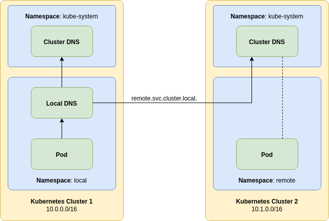
A local pod will connect to local DNS server, not the cluster default.
That pod can be a Couchbase SDK client or another Couchbase cluster as an XDCR source.
The local DNS server will capture DNS requests that are destined for the remote.svc.cluster.local. domain and forward them to a remote Kubernetes DNS server.
The Couchbase cluster we wish to connect to resides in this remote Kubernetes cluster.
Any DNS records in the remote cluster for the remote namespace will be visible to a local pod in the local cluster.
This includes individual A records for pods and SRV records generated for stable service discovery.
Any other DNS records that do not fall into the remote domain will be forwarded to the local Kubernetes cluster DNS server.
The configuration will shadow the remote namespace — if one exists — in the local cluster.
As a result, it is recommended that Couchbase server instances are provisioned in globally unique namespaces to prevent shadowing.
The following configuration is for demonstration purposes only and does not fully provide high-availability. Enterprise CoreDNS Deployment discusses improvements that can be made for production deployments.
Provisioning CoreDNS
CoreDNS is provisioned in the namespace into which your client is to be deployed. CoreDNS is deployed as follows:
apiVersion: v1
kind: ConfigMap
metadata:
  name: coredns
data:
  Corefile: |-
    remote.svc.cluster.local:5353 { (1)
      forward . 10.32.3.2 (2)
    }
    .:5353 { (3)
      forward . 10.39.240.10 (4)
    }
---
apiVersion: apps/v1
kind: Deployment
metadata:
  name: coredns
spec:
  replicas: 1
  selector:
    matchLabels:
      app: coredns
  template:
    metadata:
      labels:
        app: coredns
    spec:
      containers:
      - name: coredns
        image: coredns/coredns:1.6.6
        args:
        - '-conf'
        - '/etc/coredns/Corefile'
        ports:
        - name: dns
          containerPort: 5353
        volumeMounts:
        - name: config
          mountPath: /etc/coredns
          readOnly: true
      volumes:
      - name: config
        configMap:
          name: coredns
---
apiVersion: v1
kind: Service
metadata:
  name: coredns
spec:
  selector:
    app: coredns
  ports:
  - name: dns
    protocol: UDP
    port: 53
    targetPort: 5353
  - name: dns-tcp
    protocol: TCP
    port: 53
targetPort: 5353| 1 | This server block defines our remote namespace domain.
The remote component is the namespace we wish to forward, and can be modified as required.
Port 5353 is arbitrary, but must be greater that 1024 so that it can be opened by an unprivileged process. |
| 2 | This forwarding rule specifies that all DNS entries within the server block should be forwarded to the remote IP address.
This IP address can be determined with the command kubectl -n kube-system get endpoints on the remote cluster.
Select an IP address, or multiple IP addresses from the DNS service typically coredns or kube-dns. |
| 3 | This server block defines our default DNS server.
Port 5353 is arbitrary, but must be greater that 1024 so that it can be opened by an unprivileged process.
The port should also be the same as that used in any remote server blocks. |
| 4 | This forwarding rule specifies that all DNS entries within the server block should be forwarded to the local IP address.
This IP address should be the cluster IP address of the cluster DNS service.
It can be determined with the command kubectl -n kube-system get services on the local cluster.
The service will be named coredns, kube-dns or similar depending on your platform.
This IP address is stable. |
To get the remote DNS server, for example:
$ kubectl -n kube-system get endpoints
NAME                      ENDPOINTS                                                  AGE
kube-controller-manager   <none>                                                     39m
kube-dns                  10.1.28.194:53,10.1.90.175:53,10.1.28.194:53 + 1 more...   39m
kube-scheduler            <none>                                                     39m
You could then use 10.1.28.194.
To get the local DNS server, for example:
$ kubectl -n kube-system get svc
NAME       TYPE        CLUSTER-IP    EXTERNAL-IP   PORT(S)         AGE
kube-dns   ClusterIP   172.20.0.10   <none>        53/UDP,53/TCP   43m
You could then use 172.20.0.10.
Forwarding rules can be customized as desired per the CoreDNS documentation.
Testing CoreDNS
For the following demonstration we’ve installed the Operator and a Couchbase cluster into the remote namespace on the remote Kubernetes cluster. Much like the ping test we performed earlier, we can now test DNS and ensure we can see the remote resources:
$ ip a
1: lo: <LOOPBACK,UP,LOWER_UP> mtu 65536 qdisc noqueue state UNKNOWN group default qlen 1000
    link/loopback 00:00:00:00:00:00 brd 00:00:00:00:00:00
    inet 127.0.0.1/8 scope host lo
       valid_lft forever preferred_lft forever
3: eth0@if5: <BROADCAST,MULTICAST,UP,LOWER_UP> mtu 9001 qdisc noqueue state UP group default
    link/ether d2:f6:af:21:ac:30 brd ff:ff:ff:ff:ff:ff link-netnsid 0
    inet 10.0.53.182/32 brd 10.0.53.182 scope global eth0 (1)
       valid_lft forever preferred_lft forever
$ dig _couchbase._tcp.cb-example-srv.remote.svc.cluster.local. SRV

; <<>> DiG 9.10.3-P4-Ubuntu <<>> _couchbase._tcp.cb-example-srv.remote.svc.cluster.local. SRV
;; global options: +cmd
;; Got answer:
;; ->>HEADER<<- opcode: QUERY, status: NOERROR, id: 35383
;; flags: qr aa rd; QUERY: 1, ANSWER: 3, AUTHORITY: 0, ADDITIONAL: 4
;; WARNING: recursion requested but not available

;; OPT PSEUDOSECTION:
; EDNS: version: 0, flags:; udp: 4096
;; QUESTION SECTION:
;_couchbase._tcp.cb-example-srv.remote.svc.cluster.local. IN SRV

;; ANSWER SECTION:
_couchbase._tcp.cb-example-srv.remote.svc.cluster.local. 1 IN SRV 0 33 11210 10-1-17-231.cb-example-srv.remote.svc.cluster.local. (2)
_couchbase._tcp.cb-example-srv.remote.svc.cluster.local. 1 IN SRV 0 33 11210 10-1-46-20.cb-example-srv.remote.svc.cluster.local.
_couchbase._tcp.cb-example-srv.remote.svc.cluster.local. 1 IN SRV 0 33 11210 10-1-68-212.cb-example-srv.remote.svc.cluster.local.

;; ADDITIONAL SECTION:
10-1-17-231.cb-example-srv.remote.svc.cluster.local. 1 IN A 10.1.17.231
10-1-46-20.cb-example-srv.remote.svc.cluster.local. 1 IN A 10.1.46.20
10-1-68-212.cb-example-srv.remote.svc.cluster.local. 1 IN A 10.1.68.212

;; Query time: 48 msec
;; SERVER: 172.20.92.77#53(172.20.92.77)
;; WHEN: Tue Jan 14 12:44:27 UTC 2020
;; MSG SIZE rcvd: 661| 1 | The local host is in 10.0.0.0/16 therefore in Cluster 1. |
| 2 | An equivalent SRV lookup for the Couchbase connection string couchbase://cb-example-srv.remote.svc results in a list of A records.
These A records point to hosts in the remote cluster 10.1.0.0/16. |
Enterprise CoreDNS Deployment
The DNS deployment architecture used in this tutorial has a number of downsides that should be addressed for a production deployment. Consider the following diagram:
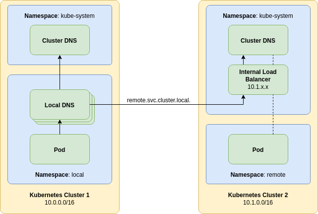
The first improvement that can be made is by having multiple local proxy DNS servers. This provides a rolling upgrade path that will result in zero downtime if an upgrade is misconfigured and a pod does not come up. Additionally pod anti-affinity should be used to prevent multiple pods being affected if a Kubernetes node goes down.
The next improvement is the addition of an internal load balancer. Some managed cloud providers allow a load balancer service to be created that has a private IP address allocated from the host VPC. This can be targeted at the remote cluster DNS deployment. By exposing the remote DNS as a service, this provides a stable IP address for the local forwarding DNS service to use.
While not depicted it is also possible to create another DNS service in the remote cluster that only forwards to the remote cluster DNS service. This raises the possibility of having that DNS service operating with the DNS over TLS (DoT) protocol. Using DoT provides a secure transport layer between the two clusters. Mutual TLS (mTLS) may also be employed in order to provide additional security.